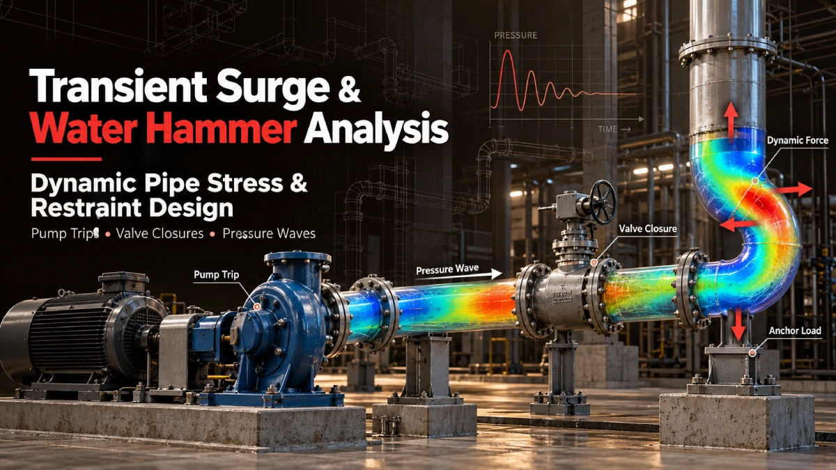
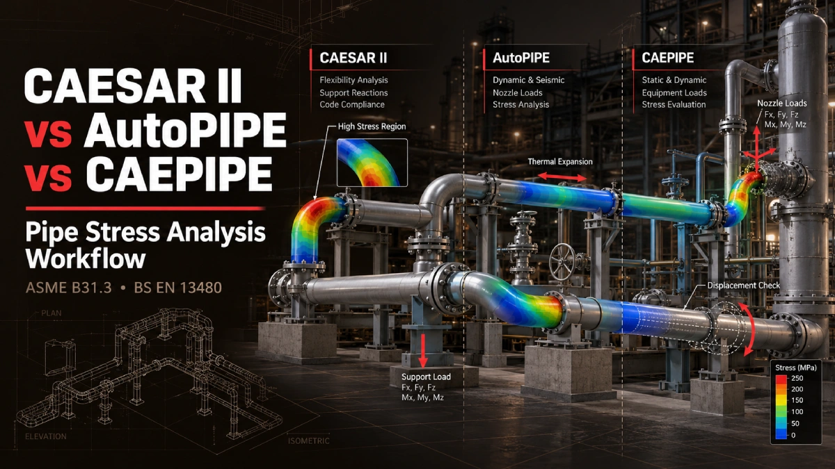
Every piping project starts with a set of constraints that have nothing to do with engineering preference. The owner may specify a stress analysis platform in the contract. The previous contractor may have left behind a model built in a different program. The project may sit under ASME B31.3 in Texas and BS EN 13480 in the north of England, with the same engineering team expected to deliver both.
For EPC engineering managers, piping stress engineers and technical procurement teams, choosing between CAESAR II, AutoPIPE and CAEPIPE is rarely a question of which program is “best”. The real question is which workflow keeps your analysis defensible, your deliverables acceptable to the client, and your schedule intact.
This CAESAR II vs AutoPIPE vs CAEPIPE pipe stress analysis comparison looks at the three platforms from a project delivery perspective. It is written for teams that rely on piping stress analysis, whether in-house or through pipe stress analysis services from a specialist partner. It covers how each handles common analysis requirements, how the governing code changes the work, what happens when a model has to move from one program to another, and when it makes sense to outsource the analysis.
Why Pipe Stress Analysis Software Selection Matters for EPC Projects
Pipe stress analysis exists to confirm that a piping system can survive its design life without overstressing the pipe, overloading connected equipment, or failing its supports. It includes pipe flexibility analysis under thermal expansion, checks of the response to sustained and occasional loads, and the forces and moments that land on nozzles, anchors and structural steel.
The software is the vehicle for that work, but the consequences of a poor match are practical:
- Incompatible models. If the client requires native model files in a specific program and your team works in another, you end up rebuilding models late in the project, when schedule pressure is highest.
- Inconsistent assumptions. Differences in how a model defines supports, friction, soil restraints or load combinations can produce results that look similar on paper but are not equivalent.
- Review friction. Owners, third-party reviewers and equipment vendors often want to open the model themselves. A deliverable they cannot open slows approval.
- Rework at handover. Legacy models inherited from a previous contractor may use conventions that no longer match the current design basis.
Software selection therefore belongs in the project execution plan from day one, alongside the piping code, the design basis and the deliverables list.
CAESAR II vs. AutoPIPE vs. CAEPIPE: Key Differences
All three programs are established tools for piping flexibility and stress analysis. Each can model beam-based piping systems, apply thermal, pressure, weight and occasional loads, evaluate stresses against a piping code, and report restraint and equipment loads. The differences that matter on a real project tend to sit in the details: supported code editions, available modules, nonlinear restraint handling, interoperability and the conventions your client already uses. CAESAR II piping stress analysis is widely encountered on process projects, so many owners and reviewers expect it, but that expectation should be confirmed with the client rather than assumed.
The table below frames the comparison criteria. Capabilities change between versions and license configurations, so every item should be confirmed against current vendor documentation before it is committed to in a scope of work.
| Comparison criteria | CAESAR II | AutoPIPE | CAEPIPE |
| Typical engineering applications | Process and industrial piping | Industrial, power and infrastructure piping | Industrial piping stress analysis |
| Piping code support | Verify supported code editions | Verify supported code editions | Verify supported code editions |
| Buried piping analysis | Evaluate available capabilities | Evaluate available capabilities | Evaluate available capabilities |
| FRP/GRE piping | Review modeling assumptions and applicable methods | Review modeling assumptions and applicable methods | Review modeling assumptions and applicable methods |
| Structural interaction | Assess coupling and modeling options | Assess coupling and modeling options | Assess coupling and modeling options |
| Equipment nozzle loads | Compare evaluation workflows | Compare evaluation workflows | Compare evaluation workflows |
| Model interoperability | Review import and export options | Review import and export options | Review import and export options |
Don’t treat any capability as universal without checking the license, installed modules, and software version. A feature available in one release or add-on may be absent in another, and a claim in a proposal that the software “can do it” is only as good as the version actually installed on the engineer’s workstation.
How Each Software Handles Complex Pipe Stress Analysis Requirements
Routine above-ground steel piping is well covered by all three platforms. The decision gets harder when the project involves unusual conditions. These are the areas where model assumptions, and not the software brand, drive the quality of the result.
Buried Piping and Soil-Structure Interaction
Underground piping behaves differently from piping on racks. The surrounding soil restrains axial and lateral movement, which changes how thermal expansion is absorbed and where stress concentrates, particularly near elbows, tees and transitions from buried to above-ground sections.
Whichever program is used, the engineer must decide how to represent soil restraint, what stiffness values to apply and how to treat the transition points. Those inputs depend on geotechnical data and judgment. The software supplies the framework, but the soil model is an engineering assumption that needs to be documented and verified.
FRP and GRE Non-Metallic Piping
Fibreglass-reinforced plastic and glass-reinforced epoxy piping do not behave like carbon steel. Their stiffness, strength and thermal characteristics differ; their allowable stresses follow different rules, and their joints and fittings often govern the design more than the straight pipe.
Metallic piping codes do not apply directly. The analysis typically follows the manufacturer’s data and the applicable design standard for the material. Because modeling approaches vary between programs and versions, teams should confirm how each platform handles non-metallic material properties and what validation the project requires before relying on the results.
Equipment Nozzle Loads and Rotating Machinery
Pumps, compressors and turbines have strict limits on the forces and moments their nozzles can tolerate. Piping that pulls on a pump casing can cause misalignment, bearing damage and seal failure long before a stress limit is exceeded in the pipe itself.
Common references include API 610 for centrifugal pumps and NEMA SM23 for steam turbines, along with vendor-specific allowable loads. The workflow is the same in any program: extract the loads at the nozzle, compare them against the applicable allowables, and adjust supports or routing until the connection is acceptable. Early coordination with the equipment vendor avoids disputes about which allowables apply.
Structural Steel and Pipe Support Interaction
Real supports are not perfectly rigid. Anchors, guides, spring hangers, and rest supports all interact with the structure that carries them. When the supporting steel deflects, the piping sees a different boundary condition than the one assumed in an idealized model.
For heavily loaded or critical lines, teams model support stiffness explicitly or coordinate with the structural group so that piping reactions are checked against structural capacity. Each platform offers ways to represent this interaction, and the right approach depends on how sensitive the system is to support flexibility.
ASME B31.3 vs. ASME B31.1 vs. BS EN 13480: What Changes in the Analysis?
The piping code defines the stress equations, allowable stresses, load combinations and documentation expected from the analysis. Switching the code changes the results, even when the geometry and the software stay the same.
ASME B31.3 for Process Piping
ASME B31.3 governs process piping in chemical plants, refineries and related facilities. ASME B31.3 process piping stress analysis typically evaluates three categories of loading: sustained loads such as pressure and weight, occasional loads such as wind, seismic or relief events, and displacement loads from thermal expansion and support movement. Each category is checked against its own allowable stress, and the displacement stress range is assessed with consideration of cyclic conditions.
ASME B31.1 for Power Piping
ASME B31.1 applies to power piping, including systems in power generation facilities. The same broad categories appear, but the equations, allowable stress rules and occasional load treatment differ from B31.3. Projects that include both process and power scope often need models set up under different codes, even when they share a plant site.
BS EN 13480 for European Metallic Industrial Piping
BS EN 13480 is the European standard for metallic industrial piping, and it is the relevant framework for many UK and European projects. Its analysis methodology, documentation structure and design conditions are not simply a relabeled version of the ASME approach. Engineers working across both regions need to apply the code’s own rules for flexibility analysis, load cases and acceptance criteria and avoid assuming equivalence with a B31 model.
A practical aid for any project is a code applicability and deliverable checklist that records the governing code and edition, the load cases required, the allowable stress basis, the software and version, and the format of every expected deliverable. Agreeing on this list at kickoff prevents most late-stage disputes.
Can You Convert an AutoPIPE Model to CAESAR II or CAEPIPE?
This is one of the most common questions from EPC teams, and the short answer is that conversion is often possible but never automatic in terms of engineering confidence.
Common Reasons EPC Contractors Need Model Conversion
- Client-required software deliverables. The owner specifies a native format, and the analysis was started in another.
- Legacy models. A previous contractor’s models arrive in a program your team does not use.
- Project handovers and subcontracting. Work moves between organizations that standardize on different platforms.
What Can Be Transferred Between Pipe Stress Platforms?
The geometric and descriptive content of a model usually transfers best. That includes pipe geometry and connectivity, material and section properties, and the basic definition of supports and restraints. Load case definitions and boundary conditions may also carry across, depending on the method used, whether that is a direct translation tool, a neutral exchange file or a manual rebuild guided by the original input.
What actually transfers depends on the software versions involved and the route chosen, so it should be tested on the specific model before a schedule is committed.
What Must Be Revalidated After Model Conversion?
Anything the translation might interpret differently has to be checked:
- Solver assumptions and code settings. Confirm the code, edition, allowable stress data and load combination rules.
- Support behavior. Gaps, friction, stiffness and nonlinear restraints are common sources of discrepancy.
- Thermal expansion and equipment nozzle loads. Check displacements and the loads at connected equipment against the original results.
- Stress results and acceptance criteria. Compare key results between the source and converted models and investigate every meaningful difference.
- Key takeaway: Model conversion is not engineering validation. An imported model needs a full technical review before you can rely on its results.
When Should EPC Contractors Outsource Pipe Stress Analysis?
Outsourced engineering services make sense when the demand on the analysis function exceeds what the internal team can deliver reliably. Typical triggers include:
- Software expertise gaps. The project specifies a platform your team rarely uses, and even an experienced pipe stress engineer needs time to reach full speed in an unfamiliar program, or the system needs modeling techniques your engineers have not applied recently.
- Compressed schedules. A late design change or accelerated milestone creates a workload peak that internal staff cannot absorb.
- Independent validation requirements. The client or a certifying body wants an independent check of critical lines or a second opinion on a disputed result.
- Multiple native deliverables. The contract calls for models in more than one software format.
- Complex piping networks. Large, highly constrained or unusual systems benefit from focused specialist attention.
A good outsourcing arrangement is not a handoff of responsibility. It is a defined scope, with agreed inputs, an agreed code and design basis, and a clear list of deliverables.
How Converge ES Supports Pipe Stress Analysis Projects
Converge ES approaches piping stress analysis as a structured engineering workflow, and our pipe stress analysis services are scoped around the client’s governing code, design conditions and required deliverables. A typical engagement follows these steps:
- Review the inputs. We review piping isometrics, design conditions and the applicable codes.
- Establish the model. We review any existing pipe stress models or build a new analysis model from the project data.
- Evaluate the load cases. We evaluate operating, sustained, thermal and occasional load cases against the governing code.
- Check equipment and supports. We review equipment nozzle loads and support reactions and identify where routing or restraint changes are needed.
- Deliver the results. We prepare stress reports, engineering recommendations and the deliverables agreed during scoping.
The software platform, file formats and reporting requirements are confirmed with you during scoping, so the output fits the way your project team and your client actually work.
Frequently Asked Questions
Which software is better for ASME B31.3 pipe stress analysis?
Can AutoPIPE models be converted to CAESAR II?
Does CAEPIPE support BS EN 13480 analysis?
What information is required to outsource pipe stress analysis?
Can pipe stress analysis be performed using existing piping isometrics?
How are pump nozzle loads evaluated during pipe stress analysis?
Need Pipe Stress Analysis for an Upcoming EPC Project?
Converge ES can review your piping analysis requirements, applicable design codes, existing models and expected engineering deliverables, then recommend a workflow that fits your project.