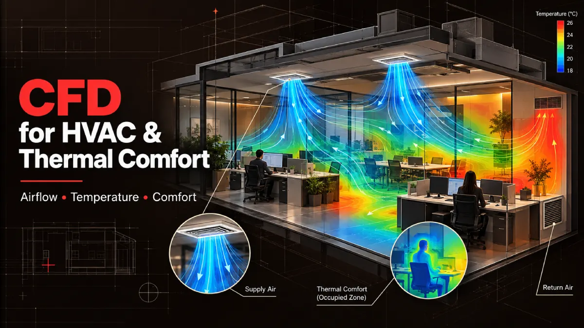
HVAC CFD analysis uses computational fluid dynamics to simulate airflow, temperature distribution, heat transfer, and related conditions within a building or HVAC system. It helps engineers identify airflow imbalances, hot and cold spots, ventilation issues, and thermal comfort concerns before changes are made to the physical system.
Unlike conventional calculations that may provide overall system-level values, CFD can show how air and temperature behave throughout a defined space. This makes it useful for investigating complex airflow patterns and evaluating design alternatives before construction, installation, or physical testing.
Converge ES provides Computational Fluid Dynamics (CFD) services covering HVAC and thermal comfort analysis, thermal flow analysis, internal and external flow analysis, and other CFD applications.
What HVAC CFD Analysis Actually Models
HVAC CFD analysis can provide detailed information about how air moves, how heat is distributed, and how environmental conditions vary throughout an occupied or conditioned space.
Airflow Distribution and Ventilation Effectiveness
Airflow distribution is one of the primary applications of CFD in HVAC engineering.
A simulation can help visualize:
- Air velocity throughout a space
- Supply-air distribution
- Return-air behaviour
- Recirculation zones
- Dead zones with limited airflow
- Airflow interaction between supply and exhaust systems
- Potential short-circuiting between supply and return air
- Ventilation effectiveness
These results can help engineers understand whether an HVAC configuration is distributing conditioned air as intended.
For example, two areas within the same building may have very different air velocities even when the overall HVAC system appears to be operating correctly. CFD can identify these localized differences and help determine whether diffuser placement, airflow rates, geometry, or other design factors need to be reconsidered.
Temperature Distribution and Thermal Gradients
Temperature is another important component of HVAC CFD.
A thermal CFD analysis can model temperature distribution throughout a space and identify areas where thermal conditions differ significantly from the intended design.
The analysis can help investigate:
- Hot spots
- Cold spots
- Temperature stratification
- Thermal gradients
- Heat accumulation
- Effects of solar or equipment heat loads
- Interaction between conditioned and unconditioned air
This can be particularly valuable in large spaces where a single average temperature does not accurately represent the conditions experienced throughout the occupied zone.
Thermal Flow Analysis as part of its CFD capabilities, supporting analysis of thermal performance for cooling and heating applications.
Thermal Comfort Modelling
Thermal comfort analysis goes beyond simply asking whether a room reaches a target temperature.
Occupants can experience different thermal conditions depending on their location, air velocity, surrounding temperatures, and other environmental factors.
CFD can therefore be used to investigate occupant-level conditions and identify areas where occupants may experience:
- Excessive air movement
- Localised cooling
- Localised heating
- Temperature differences
- Poor airflow distribution
- Areas outside the intended comfort range
Where appropriate project inputs and comfort criteria are available, the CFD results can support a more detailed assessment of indoor thermal conditions.
This is an important distinction between generic airflow simulation and a broader HVAC and thermal comfort analysis.
Contaminant and Smoke Dispersion
CFD can also be used to investigate the movement of gases, contaminants, and smoke when the required physics and project scope support it.
Potential applications can include investigating how a contaminant moves through a space, how ventilation affects dispersion, or how smoke propagates under defined fire scenarios.
The appropriate modelling approach depends on the specific application, available input data, and required analysis objectives.
When You Need HVAC CFD Analysis, and When You Don’t
CFD is a powerful engineering tool, but it is not necessary for every HVAC project.
CFD is most valuable when airflow, temperature, or thermal behaviour is sufficiently complex that simplified calculations may not provide enough information for the design decision being made.
HVAC CFD Can Be Useful For:
Data Centre Cooling
Data centres contain concentrated heat-generating equipment and require carefully controlled cooling.
CFD can help investigate:
- Cooling-air distribution
- Hot spots
- Rack-level airflow
- Supply and return paths
- Recirculation
- Cooling-system effectiveness
This can help engineering teams understand whether the planned cooling arrangement distributes conditioned air effectively.
Cleanroom Design
Cleanrooms require controlled environmental conditions and carefully managed airflow.
CFD can be used to investigate airflow patterns, temperature distribution, ventilation behaviour, and other conditions relevant to the cleanroom design.
Large Open-Plan Buildings
Large spaces such as offices, commercial facilities, terminals, warehouses, and other open environments can develop non-uniform temperature and airflow patterns.
CFD can help identify differences between occupied zones and evaluate how HVAC configuration affects the overall environment.
Industrial Ventilation
Industrial environments may involve equipment heat loads, process emissions, large spaces, and complex ventilation arrangements.
CFD can help investigate airflow paths, heat distribution, ventilation effectiveness, and the interaction between process equipment and HVAC systems.
Natural Ventilation Studies
CFD can also support studies involving naturally driven airflow.
Depending on the project, simulations may investigate how air enters, moves through, and exits a building under defined environmental conditions.
When CFD May Not Be Necessary
CFD is not automatically the right solution for every HVAC calculation.
A conventional HVAC design calculation may be sufficient when:
- The geometry is relatively simple.
- Airflow behaviour is predictable.
- There are no significant local comfort concerns.
- The design follows an established configuration.
- The engineering question can be answered through standard calculations.
- Detailed spatial information is not required.
The purpose of CFD should be to answer a specific engineering question that requires spatial simulation or more detailed physical insight.
Using a more complex simulation method does not automatically make a design better. The analysis method should match the engineering problem.
The HVAC CFD Analysis Process
A structured CFD workflow helps ensure that the simulation reflects the actual building, equipment, operating conditions, and engineering objectives.
1. Geometry or BIM Intake
The first step is collecting the geometry required for the simulation.
Depending on the project, this may include:
- Architectural drawings
- BIM models
- CAD geometry
- HVAC layouts
- Room dimensions
- Equipment locations
- Supply and return diffuser locations
- Doors and openings
- Internal partitions
- Major heat-generating equipment
The geometry is then reviewed to determine the appropriate level of modelling detail.
Where the available design information requires preparation or conversion, Converge ES also provides 3D CAD Modelling services, including simulation-ready models for CFD and FEA applications.
2. Define Boundary Conditions
The next step is establishing the operating conditions that the CFD model needs to represent.
Depending on the analysis, inputs may include:
- HVAC supply airflow
- Supply-air temperature
- Return-air conditions
- Occupancy
- Equipment heat loads
- Lighting loads
- Solar heat gains
- Wall and surface temperatures
- Outdoor conditions
- Material properties
- Ventilation rates
Accurate boundary conditions are important because the simulation results depend on the quality and relevance of the inputs.
3. Mesh and Solver Setup
The geometry is converted into a computational model and divided into a mesh.
The mesh should provide sufficient resolution in areas where important flow or thermal behaviour is expected.
Particular attention may be required around:
- HVAC diffusers
- Returns
- Equipment
- Occupied zones
- Narrow passages
- Sharp geometry changes
- Areas with expected high gradients
The solver and physical models are then configured according to the engineering problem.
CFD projects are carried out using established simulation tools selected according to the project’s physics, geometry, and engineering objectives.
4. Analyse Airflow, Temperature and Comfort Results
Once the simulation has been solved, the results can be reviewed using visual and numerical outputs.
Typical results may include:
- Velocity vector plot
- Velocity contours
- Temperature contours
- Pressure distribution
- Streamlines
- Thermal gradients
- Occupant-zone conditions
- Other project-specific comfort metrics
These results can help identify areas where the HVAC design may require modification.
5. Engineering Recommendations and Report
The final stage is translating the simulation results into engineering recommendations.
A CFD report may include:
- Project objectives
- Geometry description
- Boundary conditions
- Mesh information
- Solver methodology
- Simulation cases
- Airflow results
- Temperature results
- Thermal comfort results, where applicable
- Key observations
- Design recommendations
What to Look for in an HVAC CFD Partner
Selecting an HVAC CFD provider requires more than checking whether the company offers computational fluid dynamics.
Consider these factors when evaluating a potential engineering partner.
Experience With Your Building or System Type
Different environments create different CFD challenges.
Ask whether the engineering team has experience relevant to your application, such as:
- Data centres
- Commercial buildings
- Industrial facilities
- Cleanrooms
- HVAC equipment
- Large enclosed spaces
- Natural ventilation
The provider should understand the engineering problem rather than simply running a generic CFD simulation.
Appropriate CFD Software
Ask which software will be used and why it is appropriate for the project.
The appropriate CFD software and modelling approach are determined based on the analysis requirements, helping engineers evaluate airflow, heat transfer, pressure behaviour, and overall thermal performance.
The important consideration is how the software and modelling methodology will be applied to the specific engineering problem.
Thermal Comfort Capability
If thermal comfort is a project objective, ask what comfort-related outputs will be included in the analysis.
Depending on the project, this may involve occupant-zone temperatures, air velocities, thermal conditions, and recognised comfort metrics such as PMV/PPD where applicable.
The scope should clearly state which comfort criteria will be evaluated.
Quality and Validation Approach
CFD results depend on assumptions, geometry, boundary conditions, mesh quality, and modelling choices.
A good CFD workflow should therefore include appropriate quality checks, such as mesh refinement, sensitivity analysis, comparison against available measurements, or other validation methods where appropriate.
Design Analysis workflow includes validation processes so that simulation results can be assessed using mesh refinement studies, sensitivity analyses, and experimental comparisons when available.
Clear Deliverables and Timeline
Before starting the project, confirm:
- Number of simulation cases
- Required input data
- Analysis methodology
- Expected outputs
- Report format
- Engineering recommendations
- Number of design iterations
- Expected turnaround time
Typical CFD projects can range from a few days to several weeks depending on complexity.
Improve HVAC Performance With CFD Simulation
HVAC CFD analysis provides engineers with detailed insight into how air and heat move through a building or system. By visualising airflow distribution, temperature gradients, and thermal conditions before physical implementation, CFD can help identify potential design issues and evaluate alternative solutions.
It is particularly useful for complex environments such as data centres, cleanrooms, large open-plan spaces, industrial facilities, and projects where thermal comfort or ventilation effectiveness is a key design consideration.
Converge ES provides CFD simulation and analysis services covering HVAC and thermal comfort analysis, thermal flow analysis, internal and external flow analysis, and other engineering applications.
For projects requiring simulation as part of a broader engineering workflow, you can also explore Design Analysis services from Converge ES.
Talk to the Converge ES engineering team to discuss your HVAC CFD requirements and request a project quotation.
Frequently Asked Questions
What’s the difference between HVAC CFD and a standard HVAC load calculation?
The two approaches can therefore serve different purposes and may be used together when detailed airflow or thermal information is required.
How accurate is CFD for thermal comfort?
What do you need to start an HVAC CFD project?
The exact information required depends on the project.