Where code calculations stop, what analysis adds, and what to settle before any steel is cut
Have a vessel design heading for release? Send us the drawing and the loading list, and we will tell you what deserves a closer look.
Hi, it’s the Converge engineering team. We write about the analysis questions our clients ask before a design goes to the shop.
A vessel can pass every rule-based calculation and still crack at the nozzle, the door or the support. Our earlier guide to FEA consulting for pressure vessel design covers what the analysis evaluates. This article is about the decision point before manufacturing: where code calculations stop, what analysis adds, and what to settle before any steel is cut.
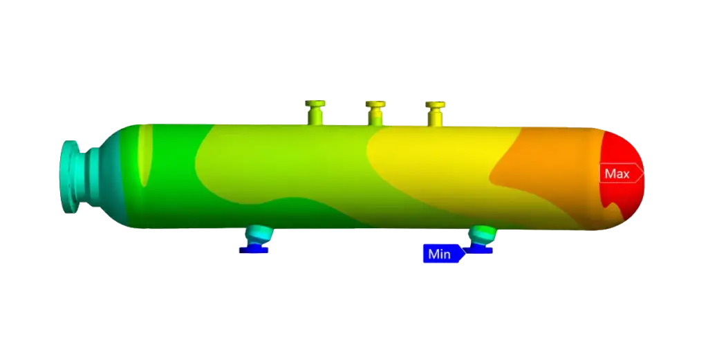
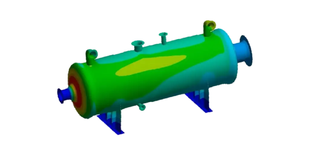
Picture a team designing a horizontal bed absorber for an air purification system. The shell thickness has been calculated to ASME Section VIII Division 1, and the numbers pass. The drawings are nearly done.
Then a senior engineer asks a plain question: what has the calculation not looked at?
The list is longer than anyone expected. Loads from the connected ductwork. The access door and its hub. The saddles. The effect of heating and cooling, over and over, for years. Nobody has a confident answer on any of them.
That is not a failure of the calculation. It was never built to answer those questions.
The code check answers one question. The vessel asks several more.
The short version:
- Design by rule (ASME Section VIII Division 1) handles common vessel geometry and loading with proven formulas.
- Design by analysis (Division 2) checks failure modes directly: plastic collapse, local failure, buckling and fatigue.
- Nozzles, doors, hubs and supports are where simple formulas run out first.
- A short list of inputs is enough to start, and most projects take from a few days to several weeks.
Why check integrity before manufacturing
Once a vessel has been rolled, welded and tested, every design change turns into cutting, welding and re-inspection. Inside the model, the same change takes an afternoon.
That is the whole case for finite element analysis at this stage. It lets you see stress, strain and deformation under realistic loads before anything is built, so problems get found when they are cheap to fix and nobody is waiting on a shop slot.
Design by rule and design by analysis
ASME Section VIII gives you two routes. They answer different questions, and plenty of real projects use both.
| Route | Typical use | What it checks |
|---|---|---|
| Division 1, design by rule | Conventional pressure vessels, storage vessels, reactors, heat exchangers | Thickness and geometry against established formulas |
| Division 2, design by analysis | Designs that need a closer look at stress, cycling or stability | Elastic and elastic-plastic behavior, fatigue, buckling, protection against plastic collapse |
A design can follow Division 1 and still have specific components analyzed to Division 2. We did exactly that on an 8 inch, 300 class nozzle: designed to Division 1 rules, then assessed to Division 2.
Which route your vessel needs depends on the code edition, the jurisdiction and your customer’s specification. Confirm it with your code engineer or authorized inspector early, before the design is frozen.
Where rule-based checks run out of road
Formulas are written for typical shapes and typical loads. The trouble starts when your vessel is less typical than the formula assumes. These are the places we look first:
- Openings and nozzles. Stress around an opening depends on the external loads on the connection, not just on internal pressure.
- Doors and hub assemblies. Closures carry their loads through bolts, hubs and locking features that a shell formula does not describe.
- Supports and attachments. Saddles, lugs and skirts create local stress where they meet the shell.
- Temperature differences. A hot side and a cooler side expand differently, and the restraint creates stress that pressure formulas never see.
- Repeated cycling. Pressure or temperature that rises and falls many times can cause fatigue long before a single load would cause damage.
- Compression and external loads. Any part of the structure under compressive stress can become unstable, which is a buckling question and not a thickness question.
None of these are exotic. All of them show up on real equipment.
What the analysis actually answers
It helps to think of each assessment as a question with a trigger. If the trigger applies to your design, the question needs an answer.
| Assessment | The question it answers | Typical trigger |
|---|---|---|
| Design by rule verification | Does the design meet the Division 1 rules as drawn? | Every vessel, as a baseline |
| Local stress evaluation | How high is stress around openings, supports and attachments? | Nozzles, lugs, saddles |
| Nozzle load assessment | Can the shell carry the loads from connected piping or ducts? | Heavy, hot or long connected lines |
| Buckling analysis | Will compressed parts become unstable? | External pressure, thin shells |
| Fatigue assessment | How many cycles can the design take? | Pressure or temperature cycling |
| Fitness-for-service evaluation | Is existing equipment safe to keep running after a change or finding? | Older vessels, modified duty |
Behind these sit the analysis types on our FEA services: static structural, thermal, dynamic, fatigue and non-linear analysis. We use tools such as ANSYS, Abaqus and SolidWorks Simulation to run them.
Why this matters for pollution control equipment
Absorbers, scrubbers, reactors and thermal oxidizers tend to combine several of the triggers above. They run hot. They connect to large ducts. They have access doors that open and close for years. Some cycle with the process.
Flow and structure are also linked. Our CFD work shows how gas moves through the equipment, and FEA checks that the structure carrying it can take what the operating conditions throw at it. Doing both early means the flow design and the mechanical design agree before drawings are released.
Four recent projects
Client details stay confidential, but the work itself shows where analysis earns its place:
- Horizontal bed absorber for air purification. A fatigue calculation and strength evaluation of the vessel.
- Door and hub assembly. A structural integrity evaluation under ASME Section VIII Division 2, Part 5.
- 8 inch, 300 class nozzle. Designed to Division 1, stress analyzed to Division 2.
- Ventilator equipment door assembly. A structural integrity check under Division 2.
Look at what three of the four have in common: openings and closures. The shell body is rarely where the surprises are.
What to hand over so the analysis can start
We need five things to begin: the geometry, the material properties, the load conditions, the constraints, and what you want the analysis to prove. For a vessel, these details make the work faster and the results more useful:
- Design pressure and design temperature, plus normal operating conditions
- A nozzle load schedule, or at least the weights and temperatures of connected lines
- The support arrangement and anchoring
- The expected number of pressure or temperature cycles, if fatigue could matter
- The code edition and any customer specification
Most projects run from a few days to several weeks, depending on complexity. The quality of the result also depends on the quality of the inputs, so a short call to settle the assumptions is time well spent.
Questions to ask before approving a design for fabrication
Put these to your design team, your supplier or us:
- Which loads has the calculation not covered: connected piping, thermal gradients, cycling?
- Which openings, doors or supports see the highest local stress?
- Does any part of the vessel see compression or external pressure?
- Is cycle life a requirement, and has it been checked?
- Who reviews and signs off the analysis report?
If the answer is “we assumed,” ask what the assumption rests on.
Thanks for reading the Converge blog. Have a vessel design coming up for release? Send it over and we will take a look.
The takeaway
A passed code check is a starting point. Analysis tells you what the check could not see, and it does it while changes are still cheap.
Here is the checklist:
Collect these
- Design drawings and the code edition
- Pressure and temperature conditions, including cycling
- The nozzle load list and support details
- Material data
Decide these
- Which parts need analysis beyond the rule-based check
- Whether cycling calls for a fatigue assessment
Ask for these
- A report with clear pass or fail criteria
- A list of the assumptions behind the results
Then, as you go
- Feed every design change back into the model before release
- Keep the final report with the vessel documentation
What else you should know:
- FEA services: See everything we analyze, from structures to piping, on our Finite Element Analysis page.
- Keep reading: Rework is where missed loads turn into cost. Read Reducing Equipment Manufacturing Rework Through FEA-Based Design Validation.
- Pipe loads: Piping forces feed the vessel check. See how to choose a pipe stress workflow.