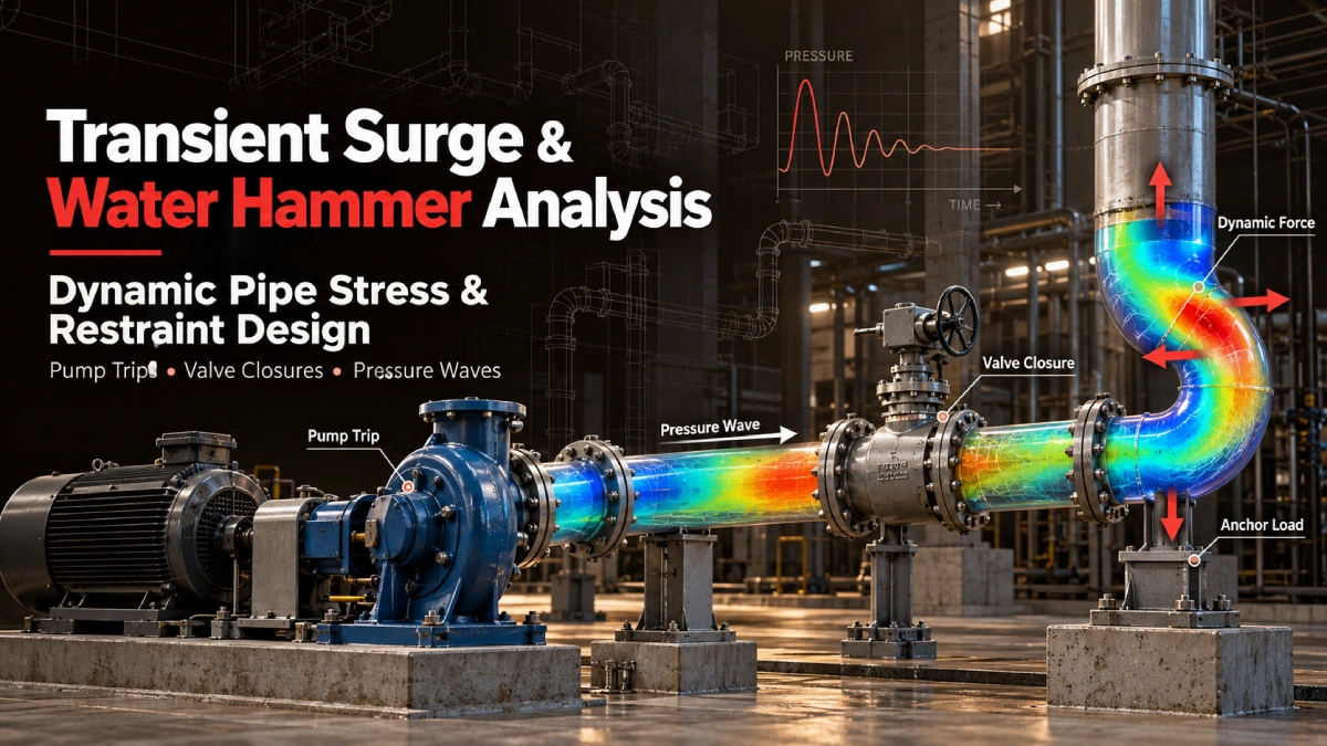
A pump trips at the end of a long transfer line. The fluid in the discharge pipe is still moving, but nothing is driving it any more. Pressure at the pump falls, a wave travels down the line at the speed of sound in the fluid, the check valve closes, and the wave reflects back as a sharp pressure rise. In a few seconds, the piping has seen pressure swings and unbalanced forces that its steady-state design never accounted for.
Events like this are routine in industrial piping and pumping networks. Pump trips, rapid valve closures and emergency shutdowns all change fluid velocity faster than the system can absorb, and the result is a pressure wave that loads the pipe, the supports and the connected equipment. In the worst cases, it damages anchors, displaces pipe off its supports or overloads a pump nozzle.
Hydraulic transient analysis tells you what the fluid does. Pipe stress analysis tells you how the pipe and its restraints respond. For many systems, the two studies have to be coordinated, because the output of one is the input to the other. This article explains how that integration works, where it goes wrong, and what EPC contractors should expect from a combined study.
What Is Transient Surge and Water Hammer Analysis?
Surge analysis and water hammer analysis both describe the study of rapid pressure and flow changes in a liquid-filled piping system. The terms are often used interchangeably. Water hammer usually refers to the pressure waves caused by fast changes in velocity, while surge analysis is the broader study of the transient behaviour of the whole system, including protection devices and column separation. Pressure surge analysis is the part of that study that quantifies the pressure peaks and troughs themselves.
How Pressure Transients Develop in Piping Systems
A transient begins whenever the flow is forced to change quickly. The moving fluid has momentum, and when a valve closes or a pump stops, that momentum has to go somewhere. The result is a pressure wave that travels through the system. Four factors shape what happens next:
- Rapid changes in fluid velocity. The faster the change, the larger the pressure disturbance.
- Pressure wave propagation. The wave moves at a speed set by the fluid, the pipe material and the wall thickness.
- Wave reflection. Waves reflect and combine at valves, pumps, junctions, tanks and other boundaries, so the highest pressure may occur well away from the source of the event.
- System configuration and fluid properties. Pipe length, elevation profile, fluid density and vapour pressure all influence how severe the transient becomes.
Common Events That Trigger Water Hammer
- Pump trips and emergency shutdowns, where loss of power stops the pump and the flow decelerates rapidly.
- Rapid valve closures, especially on long lines carrying high-velocity liquid.
- Pump startup and restart, which can send a pressure wave into a line that is partly empty or already moving.
- Check valve slam, when a check valve closes late against reversing flow.
- Sudden changes in flow direction, such as those caused by operator action or control failures.
Why Static Pipe Stress Analysis Alone Cannot Capture Water Hammer Risks
A conventional pipe stress analysis evaluates the system under sustained, thermal and occasional loads, and most of those are treated as static or equivalent static. Water hammer is different in kind. It is a time-dependent event in which pressure and force vary quickly, and the structure responds dynamically.
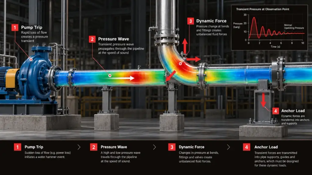
- Steady-state pressure and transient pressure are different quantities. The design pressure on the line list does not describe what the pipe sees during a trip.
- Static evaluation has limits. Treating a dynamic event as a single static load can miss the timing and direction of the forces, and either overstate or understate the demand on restraints.
- Supports, anchors, joints and equipment are all affected. A force that acts for a fraction of a second can still exceed the capacity of a guide or an anchor.
- Time matters. The structural response depends on how quickly the force changes compared with the natural frequency of the piping and its supports.
Which Industrial Systems Require Surge and Water Hammer Analysis?
Any liquid system with significant flow velocity, long pipe runs or fast-acting valves is a candidate. Four categories come up most often on EPC projects.
Water Transmission and Pumping Stations
Long transmission mains and booster stations are classic surge cases. A pump trip can cause a deep pressure drop followed by a damaging rebound, so pipeline surge analysis services for these systems usually define the surge protection needed for the line.
Oil, Gas and Refinery Transfer Lines
Liquid transfer systems with fast valve operations can generate severe transients, particularly during emergency shutdown. The study identifies safe valve closure times and the loads that follow.
LNG and Industrial Loading Systems
Loading and unloading lines experience transients when flow is started, stopped or diverted. ESD valve closure sequences are a key scenario, and the resulting forces have to be considered when restraints are designed.
Firewater and Critical Utility Systems
Firewater networks must work on demand. Pump startup, shutdown and changing demand cause pressure fluctuations across the network, and the piping must survive them without losing function when it matters most. A fire water system surge analysis checks how pump starts, stops and valve operations load the network, and a hydraulic study of the firewater system often sits in the same scope.
Step-by-Step Workflow: Integrating Surge Analysis with Pipe Stress Analysis
The value of a combined study comes from a disciplined hand-off between the hydraulic model and the structural model. The workflow below describes the sequence used on well-run projects.
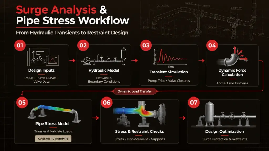
Step 1: Collect Hydraulic and Piping Design Inputs
The quality of the result depends on the quality of the inputs. Gather the following before modeling begins:
- P&IDs and piping isometrics.
- Pump curves and operating conditions.
- Valve characteristics and closure times.
- Pipe sizes, elevations, materials and wall thicknesses.
- Fluid properties and boundary conditions.
Step 2: Build the Hydraulic Transient Model
Develop the network representation, define the operating conditions and the transient events to be studied, and set the relevant hydraulic boundary conditions. Validate the steady-state model before running any transient simulation. If the steady-state flows and pressures do not match the design, the transient results cannot be trusted.
Step 3: Simulate Pump Trips, Valve Closures and ESD Scenarios
Identify the critical operating scenarios and run them. For each one, calculate the transient pressure histories, review the maximum and minimum pressures along the line, and identify the locations most exposed to severe transients. Low pressure matters as much as high pressure, because it can lead to vapor formation and column separation.
Step 4: Calculate Dynamic Unbalanced Forces
Pressure waves create forces wherever the flow path changes direction or area. Derive the time-dependent forces at elbows, tees, reducers and other relevant components, keeping both direction and timing. Use these results to identify the critical piping segments and the restraint locations that carry the load.
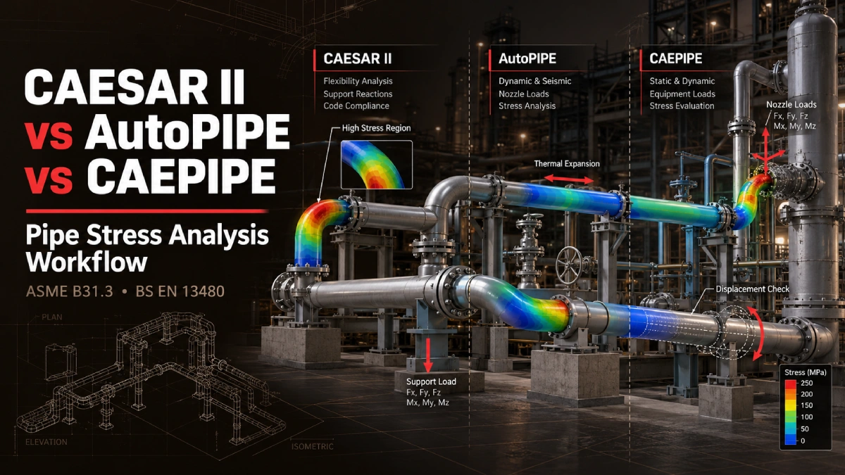
Step 5: Transfer Dynamic Loads into CAESAR II or AutoPIPE
Translate the hydraulic outputs into load definitions the structural model can use. This means coordinating node locations and force directions between the two models, then applying a compatible time-history method or another dynamic analysis approach that can be justified for the system. Validate the force units, timing, boundary conditions and solver assumptions before relying on the response.
Technical note: The data transfer procedure depends on the software, the version, the available modules and the chosen analysis method. Do not assume that a hydraulic transient program such as PIPENET or AFT Impulse produces a file that a pipe stress program can read directly. Confirm the exchange route for your specific tools, and expect some data preparation.
Step 6: Evaluate Pipe Stress and Restraint Loads
With the dynamic loads applied, review the structural response:
- Dynamic stress and displacement response of the piping.
- Anchor and guide reactions.
- Loads at equipment connections.
- Any need for additional supports or restraint modifications.
Step 7: Optimize Surge Protection and Pipe Restraint Design
If the results are not acceptable, the fix may be hydraulic, structural or both. Options include surge vessels and other hydraulic protection devices, adjusting valve closure times, and modifying the supports or restraints. After every change, repeat the simulations to confirm that the design improved and that the change did not create a new problem elsewhere.
PIPENET vs. AFT Impulse: Selecting a Hydraulic Transient Analysis Tool
PIPENET and AFT Impulse are both widely used for hydraulic transient work. The right choice depends on the project and on what the downstream structural workflow needs. The comparison areas below are the ones that matter in practice. Neither tool should be treated as categorically more accurate than the other; accuracy depends on the quality of the model, the inputs and the validation.
| Comparison area | Discussion points |
| Modeling scope | Network topology and transient scenario requirements |
| Pump trip simulation | Pump inertia, operating conditions and trip behavior |
| Valve closure modeling | Closure characteristics and transient response |
| Transient output | Pressure, flow and force-related data availability |
| Structural integration | Export formats and data preparation requirements |
| Engineering deliverables | Results, reports and validation requirements |
How Surge Analysis Influences Pipe Support and Restraint Design
Anchor and Guide Load Evaluation
Surge results show how unbalanced forces are distributed along the line and which restraints carry them. That defines the load path from the pipe into the supports, and it allows the support capacity to be verified against the actual dynamic demand.
Snubber and Dynamic Restraint Requirements
Where displacement must be controlled under a fast event but free movement is needed for thermal expansion, dynamic restraints may be considered. Their selection has to be coordinated with the flexibility requirements of the piping, since a restraint that solves the dynamic problem can create a thermal one.
Surge Vessels and Pressure Protection Systems
Hydraulic mitigation reduces the transient at its source, while structural mitigation strengthens the system to withstand it. The most economical solution usually combines the two, and finding the balance takes iteration between the hydraulic and structural models.
Common Engineering Mistakes in Water Hammer and Dynamic Pipe Stress Analysis
- Assuming that maximum pressure and maximum structural force occur at the same moment. They often do not, and the force that governs restraint design can occur at a different time.
- Applying transient peak pressures as the only structural loading. Pressure peaks alone do not describe the unbalanced forces acting on the pipe.
- Ignoring check valve closure characteristics. Slow or late closure changes the transient significantly.
- Using incorrect fluid properties or wave speeds. Errors here move the whole result.
- Neglecting support stiffness and restraint behavior. The structure responds according to how it is actually restrained.
- Failing to validate transferred time-history forces. A units error or a timing mismatch between models can invalidate the study.
What Deliverables Should EPC Contractors Expect from a Combined Surge and Pipe Stress Study?
The scope should be defined before work begins. A combined study typically produces the following:
| Engineering deliverable | Purpose |
| Hydraulic transient model | Simulate critical operating events |
| Pressure envelope plots | Identify maximum and minimum transient pressures |
| Dynamic force-time histories | Define structural transient loads |
| Pipe stress analysis results | Evaluate structural response |
| Anchor and support load summary | Support restraint and structural design |
| Mitigation recommendations | Reduce unacceptable hydraulic or structural risks |
| Final engineering report | Document assumptions, results and recommendations |
How Converge ES Supports Surge and Pipe Stress Engineering Projects
Converge ES delivers transient surge and water hammer analysis services as one coordinated engineering effort with pipe stress analysis. The scope for each project is agreed during an initial review of the hydraulic and piping design, and typically covers:
- Initial hydraulic and piping design review.
- Identification of critical transient scenarios.
- Hydraulic transient simulation.
- Dynamic force evaluation.
- Pipe stress and restraint analysis.
- Design recommendations and reporting.
The tools, file formats and deliverables for your project are confirmed with you during scoping, so the study fits your engineering workflow and the requirements of your client.