How checking the design first takes the costly surprises out of fabrication
Releasing a design soon? Book a design validation review before the drawings go to the shop.
Hi, it’s the Converge engineering team. We write about the analysis questions our clients ask before a design goes to the shop.
Rework is a design problem that shows up as a fabrication bill. If you want the deep dive on one equipment type, start with our guide to FEA for pressure vessels. This article covers all types of process and pollution control equipment, and the practical side: where rework comes from, how design validation works, and what to check before every release.
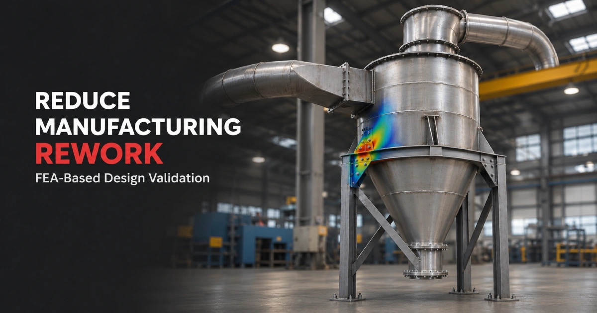
Picture a cyclone separator on a process line. It is built to the drawing, passes inspection and gets installed. A few weeks into operation, cracks appear near a support bracket and the cone starts to distort.
The fix is quick enough. Stiffeners are cut, fitted and welded on. The harder part is the schedule, which slips, and the conversation afterward. Which load did we miss, and why did nobody see it?
The welds were fine. The load path was never checked.
The short version:
- Most rework starts as an unchecked load or an untested assumption, not a shop mistake.
- FEA lets you change a model before you change steel.
- It works best alongside CFD, pipe stress and CAD, not on its own.
- Track three or four simple numbers so the payoff is visible.
Where rework really comes from
When we look back at problems found late, the same causes keep turning up:
- Loads nobody listed. Wind, lifting, transport, and forces from connected piping or ducts.
- Local stress at attachments. Supports, lugs, openings and doors concentrate stress in small areas.
- Thermal movement. Parts that grow when hot, but are held in place, push back on whatever holds them.
- Vibration. Fans and rotating equipment can excite a structure that was only checked for static loads.
- Assumed thickness and material. Chosen from habit or from the last project, not from the loads on this one.
- Handover gaps. Analysis and drawings that no longer match after a late design change.
Each of these can be found before fabrication. Very few are easy to find after.
What design validation looks like in practice
Design validation is simply checking that a design will cope with the conditions it will face, before it is built. With FEA, the process looks like this:
- Gather the inputs. Geometry, material properties, load conditions, constraints and the questions you want answered.
- Build the model. A digital version of the equipment, simplified where it is safe to do so.
- Apply loads and supports. Pressure, temperature, weight, external loads and how the equipment is held.
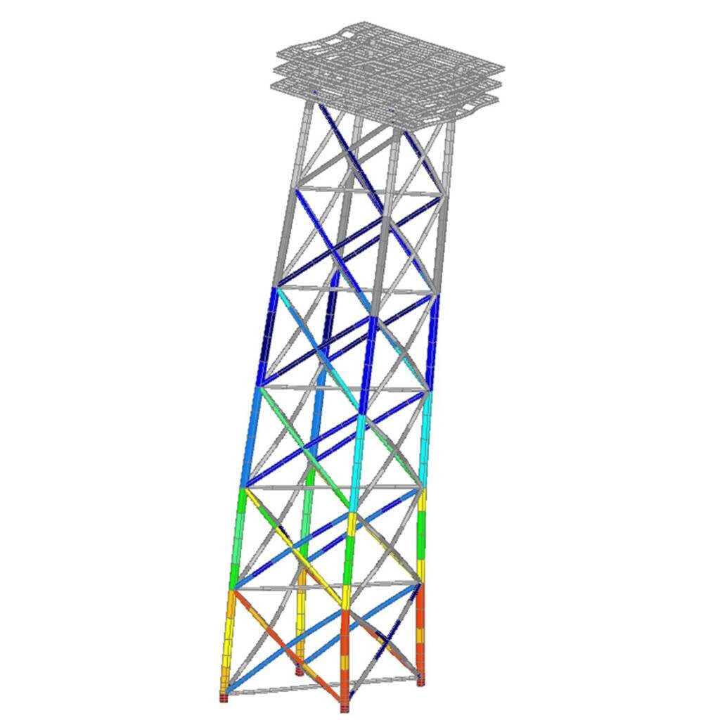
- Review the results. Stress, deformation and any parts running close to their limits.
- Change the design in the model. Try the stiffener, the thicker plate or the moved support, and run it again.
- Report. Clear findings, stated assumptions and recommended changes.
The analysis type follows the cause of the rework:
| Rework cause | Analysis that finds it |
|---|---|
| Missed or underestimated loads | Static structural analysis |
| Restrained thermal growth | Thermal analysis |
| Vibration and resonance | Dynamic analysis |
| Cracks after repeated cycling | Fatigue analysis |
| Large deformation or complex material behavior | Non-linear analysis |
All five are part of our FEA services, and the output is a report meant to guide a decision, not just a stack of plots.
Which equipment benefits most
Almost any fabricated equipment can benefit, but some designs have rework risks that show up again and again. This table shows where we usually look first:
| Equipment | Typical rework risk | What to check |
|---|---|---|
| Cyclone separator | Cracking or distortion at supports and the cone | Support loads, thermal growth |
| Baghouse | Housing and hopper deformation under pressure or suction | Panel stiffness, support structure |
| Thermal oxidizer | Shell stress at high operating temperature | Thermal stress, restrained growth |
| Scrubber | Local stress at nozzles and supports | Nozzle loads, wind and weight |
| Electrostatic precipitator | Large panels moving under load | Stiffener layout, support design |
| Duct network | Support spacing and expansion problems | Thermal expansion, vibration |
| Boiler or HRSG | Stress from temperature differences | Thermal stress, pressure parts |
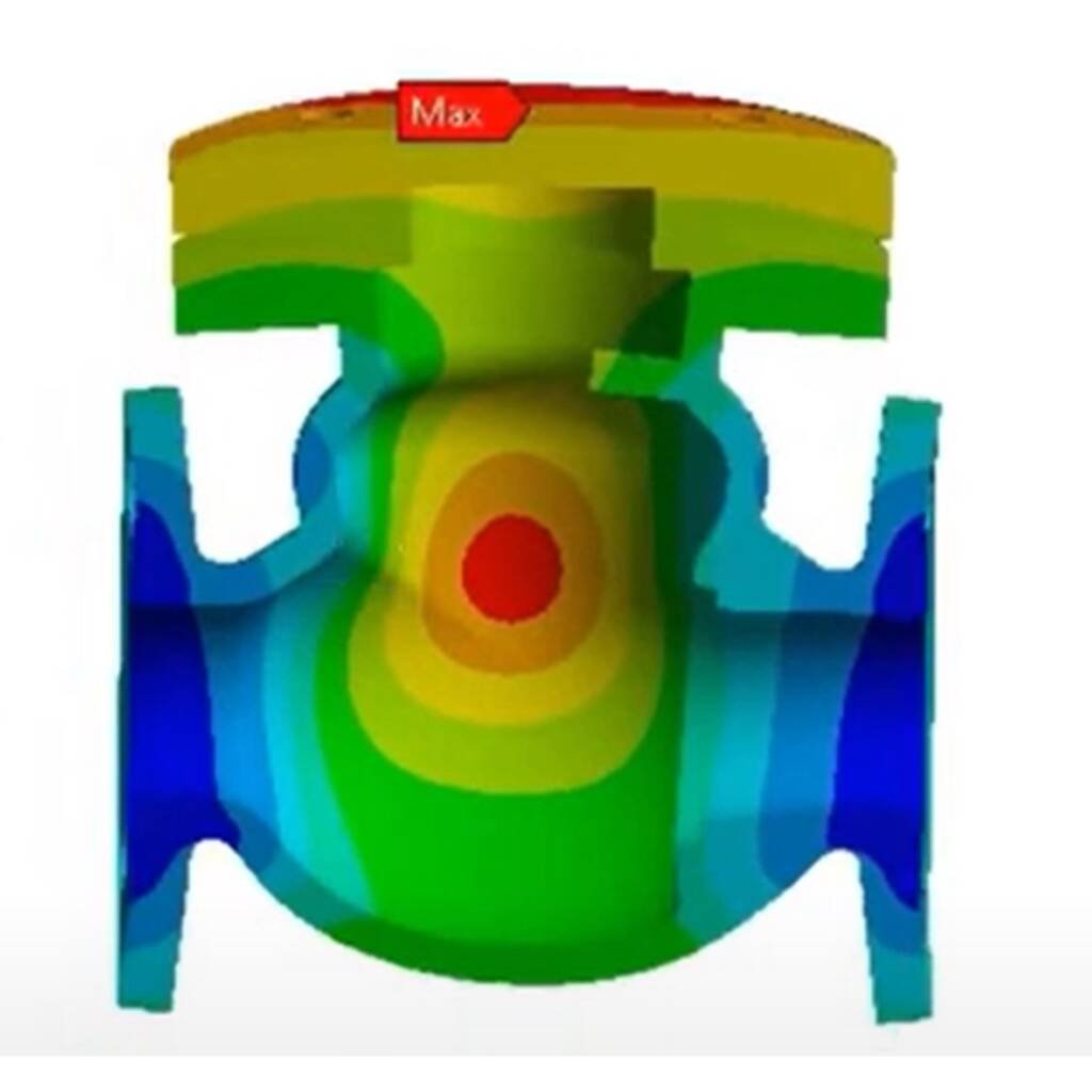
| Valve | Body stress under pressure and temperature | Structural and thermal FEA |
The list is a starting point, not a rulebook. Your own duty conditions decide what matters.
FEA and CFD, working together
Flow creates loads. Gas moving through a duct or a boiler sets the pressure and the temperature the structure has to carry. Our CFD analysis shows how the flow behaves, and FEA checks how the structure responds.

When a design depends on both, running them in the right order avoids a second round of changes. Settle the flow first, then check the structure that carries it.
FEA and pipe stress
Piping pushes back on equipment. The loads at a nozzle come from the piping system, and they become inputs to the vessel or equipment check. If they are wrong, the local stress is wrong too.
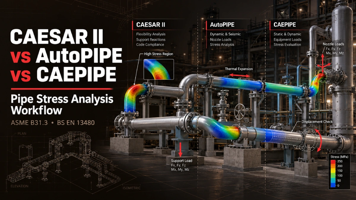
That link also runs through surge events, because a pressure transient changes the forces in the line. We cover both topics in our posts on pipe stress analysis workflows and transient surge and water hammer analysis.
From validated model to fabrication drawings
Validation only reduces rework if what you validated is what gets built. That means the analysis model, the 3D model and the shop drawings need to describe the same design.
This is where the engineering side and the manufacturing side meet. A validated geometry flows into 3D CAD modelling, then into 2D drafting for the shop, and on to machining and fabrication. One model and one set of drawings means fewer places for a late change to slip through.
Measuring the payoff
The easiest way to see whether validation is working is to count. Start with the last few projects, then repeat after you add FEA to the release process. Copy this table and fill it in:
| Measure | Before FEA validation | After FEA validation |
|---|---|---|
| Design revisions after release | ||
| Shop floor change orders | ||
| Reinforcement added after build | ||
| Days from release to shipment |
Pro-tip: Log the cause of every post-release change, not just the cost. After a few projects, the pattern tells you exactly which analysis to run earlier.
A design release checklist
Before the drawings leave engineering, ask:
- Have all external loads been listed and signed off?
- Have the highest local stress points been identified?
- Is thermal movement allowed for?
- Does the structure stay clear of the operating frequency of connected fans or machinery?
- Do the drawings match the latest analyzed model?
A design is ready for release when its loads are known, not when its drawings are finished.
Thanks for reading the Converge blog. Want a second pair of eyes on a design before it goes to fabrication?
The takeaway
The cheapest fix is the one made in the model. Validation will not remove every surprise, but it removes the ones that come from loads nobody checked.
Here is the checklist:
Collect these
- The load list and operating conditions
- Current drawings and material data
- Records of rework on recent projects
Decide these
- Which equipment types get validated first
- Which parts of each design carry the most risk
Ask for these
- A short report with assumptions, results and recommended changes
- A clear statement of what the analysis did not cover
Then, as you go
- Log every post-release change and its cause
- Update the model whenever the design changes
What else you should know:
- FEA services: Explore structural, thermal, dynamic, fatigue and non-linear analysis on our Finite Element Analysis page.
- Keep reading: For one equipment type in depth, read FEA for Pressure Vessels: Evaluating Structural Integrity Before Manufacturing.
- Manufacturing support: From validated design to finished part, see our Manufacturing and Fabrication services.